ADC
An explanation of TWELITE's ADC.
ADC Overview
The TWELITE has a 10-bit, 4-channel ADC (ADC2 is shared with the VREF input, ADC3 and 4 are shared with DIO). (ADC2 is shared with the VREF input, and ADC3 and 4 are shared with DIO.
The reference voltage of the ADC, Vref, is approximately 1.235V and there is no external output. No information on temperature characteristics is available.
The ADC range is 0-Vref or 0-2Vref. (It is not a relative scale of 0-Vcc)
For ADC measurements, the Vref or range determines the supply voltage required to achieve the performance on the datasheet. (>2.2V for 0-Vref, >2.6V for 0-2Vref)
Although the ADC can measure multiple ports, it cannot measure multiple ports at the same time because it is switched by a multiplexer. To measure multiple ports, the ports are switched sequentially.
If accuracy is required, the use of an external ADC is recommended.
The ADC allows you to set the sampling clock of the sampling circuit at 2Mhz, 1Mhz, 500khz, 250khz (500khz recommended). This is not the actual sampling clock, it is the frequency of the internal circuitry. If you want to sample at regular intervals, you can use a periodic timer (TickTimer or TIMER0/1/2) interrupt as the starting point for the software to acquire the sample values. However, at high periods, it is necessary to take into account jitter in the timer's time axis.
Each sample acquisition requires (2, 4, 6, 8) x 3 + 14 sampling clocks.
t 500khz and 2 clocks, this gives 2x3+14 = 20 sampling clocks = 40 usec.
ADC Ports
Ports
Remark
Supply voltage
To measure the supply voltage, which is divided by 2/3, the ADC value is converted to mV and then multiplied by 3/2. For simplicity, it is {ADC value (0-1023)} x 3705 / 1024.
Temperature sensor
A built-in temperature sensor measures in the 0-Vref range. It has a large offset error and requires calibration. It is not used in TWENET.
ADC1
This is a dedicated analogue port.
ADC2 (VREF)
This is a dedicated analogue port. Note: ADC2 can be used as a reference voltage input as VREF (VREF external input is not used on TWENET).
ADC3,4
It is shared with DIO(digital port), so the internal pull-up must be disabled.
Input circuit
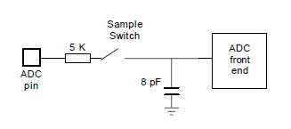
The input circuit of the ADC can be modelled as shown in the diagram. The series resistance is between 5kΩ and 10kΩ (in the diagram it is 5kΩ). This can be used as a reference for designing the external circuit.

When measuring a voltage value that is divided by a high resistance value, for example 1 MΩ, a capacitor is added to the output end. This capacitor reduces the response to voltage changes but stabilises the measured voltage.
Source code in TWENET
For ADC measurements, we use adc.c, which summarizes the Peripheral API procedures.
最終更新